I have to go back...
That was the final conclusion I reached researching myriad ways of hooking up Firewire based Standard Definition NTSC and PAL video capture hardware.
It certainly wasn't arrived at easily.
I fought and tried many ways of trying this gear out with modern Post-Intel Mac mini PCs.. even contemplated virtual machines running QEMU for a time.
But in the end, I started hunting eBay and found (just enough) parts and pieces to assemble a gosh darn it honest to gawd PowerPC (PPC) Mac mini.
As it arrived it had some vintage of OS X 10.4 but that was not old enough.
So I looked far and wide to find a real set of mac mini initial installation CD/DVD roms for OS X 10.3.7
Simply Amazing.. this is the year 2019 mid December..
It wasn't without peril.
I first replaced the HDD with a (PATA) SSD, that's an IDE interface for those playing at home.
I thought about using an M.2 NVMe drive.. but nothing would translate it to IDE and still fit in the original case. Then I found a M.2 mSATA carrier which might work.. but it was using TLC chips meaning it would only last 1-2 years max.. so I search for SLC.. and couldn't find any.
Finally I settled on MLC (it was good enough for most laptops) and found a few brand new PATA MLC drives.. on Amazon no less.
On first boot.. I got nothing.. no drive detected from the OS X installer.
I didn't know the drive had to be pre-formatted with a partition.. And I didn't know you had to pre-format it (before) starting the installer or it would show up with a great big Red ! (bang) on the drive icon.
Finally I powered down, pressed the power button while pressing 'C' and got into the Installer menu to Disk Utility (before) running the Installer.. and selected 'Erase as Mac Journaled file system' without the options to write zeros to wipe the drive.. as an SSD.. why burn a write cycle?
It finished erasing the SSD and re-pre-formatting it for Mac. I exited the Disk Utility and bounced into the Installer.. it detected the properly formatted drive (no.. Red ! bang) and continued the installation.
The old Super Drive rattles like a train running down a railroad track.. and its slow as Christmas at installing.. but its chugging along and looks like its going to complete. I feel positively dental.. this is like installing Windows XP.. only Apple style.
10/10/2019
Fixing USP Nut 0.8.6 for Cacti 1.2.2
Eric A. Hall wrote a nice monitoring package for Cacti in PHP and XML.
Originally you copied one script and two xml files into place and then configured Cacti to enable the monitoring script and import the XML template for the Data graphs. But these were written for Cacti 0.8.6 or 0.8.7
The default install for Cacti for Raspberry Pi is version 1.2.2 and the monitoring package fails to work as described for the newer version of Cacti.
Here is how to get it working.
First connect the UPS to the raspberry pi using a USB cable
Second setup the NUT monitoring demon on the raspberry pi, as standalone and as the master monitoring daemon for the UPS.
This has been tested with my example:
cyberpower1:
CyberPower CP1500PFCLCD

edit # vi nut_ups_status.xml
add the second line below to the file, use the first line below as a locator to find the right place to put the second line in the file
<arg_get>get</arg_get>
<arg_num_indexes>num_indexes</arg_num_indexes>
edit # vi ss_nut_ups_status.php
remove the first line from the file
add the following lines to the top of the file
#!/bin/php -q
<?php
error_reporting(0);
include_once(dirname(__FILE__) . '/../include/cli_check.php');
[You can test this script modification from the command line.]
# php ss_nut_ups_status.php localhost:: query ups.description
It should return:
root@raspberrypi:/home/pi/cacti-nut/scripts#
php ss_nut_ups_status.php localhost:: query ups.description
cyberpower1:CyberPower CP1500PFCLCD
cyberpower1:CyberPower CP1500PFCLCD
Third install the script and the two xml files to the <cacti_path> = /usr/share/cacti/site/
move the ss_nut_ups_status.php script into its home directory /usr/share/cacti/site/scripts
move the nut_ups_status.xml file into its home directory /usr/share/cacti/site/resource/script_server/
move the nut_ups_status.xml file into its home directory /usr/share/cacti/site/resource/script_server/
import the template nut_ups_status_data_query.xml from it current location using the cacti Template Import wizard to navigate the file system and import the nut_ups_status.xml file
Everything else works as previously described by Eric Hall.
Basically it works by executing a PHP script to open a TCP socket connection to the upsd monitoring daemon. You can do this too by installing telnet and then using it to connect to the upsd daemon like this:
telnet localhost 3493
Trying ::1...
Connected to localhost.
Escape character is '^]'.
help
Commands:
Trying ::1...
Connected to localhost.
Escape character is '^]'.
help
Commands:
HELP VER GET LIST SET INSTCMD LOGIN LOGOUT USERNAME PASSWORD STARTTLS
ver
Network UPS Tools upsd 2.7.4 - http://www.networkupstools.org/
Network UPS Tools upsd 2.7.4 - http://www.networkupstools.org/
list ups
BEGIN LIST UPS
UPS cyberpower1 "CyberPower CP1500PFCLCD"
END LIST UPS
BEGIN LIST UPS
UPS cyberpower1 "CyberPower CP1500PFCLCD"
END LIST UPS
The "magic" of this monitoring package however is it quickly sets up a data source and graphing templates within cacti and instructs cacti how to interpret and graph the data in cacti terms with very little user input.
Previous error messages I received while figuring this out were:
# php ss_nut_ups_status.php
PHP Notice: Undefined index: REQUEST_URI in /usr/share/cacti/site/include/global.php on line 425
Previous error messages I received while figuring this out were:
# php ss_nut_ups_status.php
PHP Notice: Undefined index: REQUEST_URI in /usr/share/cacti/site/include/global.php on line 425
This is a LOW LEVEL "notification" all it means is that the line (indicated '425') in the global.php file tested for an environment variable that was not set, it is "in fact" never set for any php script execucted from the command line and can be safely ignored.
The following line added to the top of the #ss_nut_ups_status.php script basically "turns" that distracting notification "off".. otherwise even when it was working properly the notification would continuously show up.
error_reporting(0);
And when trying to add the Data query type to the [Device] for the local raspberry pi acting as the UPS monitoring server.. the query type was not "actived" (By DEFAULT no new data query just added or created is activated. Its a separate step to turn it on.) This has to be done on the Data Query page for the UPS Nut configuration page. The Rpi (Node) can't use the Query type until its "activated".
And when Importing the Template there is a (New) feature in Cacti 1.2.2 that (auto-enables) a feature called ('Preview') which "fakes" you out by making you think it has imported the Template.. but look very closely and in small, tiny print, it says.. "This is what it would have done if Preview was not enabled !!!" You have to slide or de-checkify (depends on the Console 'Theme' and Browser type which kind of de-checkify you have to do.. to turn-preview-off !!!)
If you don't already have the Data Query "activated" on it config page, when you try to Import the Template.. many things will "Fail".. activate the Data query "first" and then try Importing again..
It will Import 100 percent correct and nothing fails.
After adding the Data Query to the Device as an [Associated Data Queries] entry, it enables a realtime Debug tool called ['Actions'] over to the right for the Data Query line for [Nut - UPS Statistics]
They appear as a "refresh" green circular chasing arrows icon, and a "verbose" yellow circular chasing arrows icon. And a "remove query" red ex.
Clicking on the "yellow" will run run a query and popup the results above the [Associated Data Queries] (section) .. if it says something about "XML and Unsupported" that means the [mandatory] ss_script line in the XML file is missing:
edit # vi nut_ups_status.xml
add the second line below the first line to the file, use the first line only as a guide to where ot place the second line in the file
<arg_get>get</arg_get>
<arg_num_indexes>num_indexes</arg_num_indexes>
10/07/2019
The Lightning Detector 52pi and Me
So I've been spending some time with Raspberry Pi's lately.
Normally I like the Google Nest products.. and I still do a lot of that.. but their organizational changes and Googles habit of canceling things without warning has got me back in the mode of "Can I do this myself?"
I had been enthralled with the $5 PiZero for a couple years.. and barely got Teamviewer or VNC server to work on one.. mostly through x86 emulation.. and that was not easy.
This year I finally upgraded to RPi 3b+ just before the RPi 4 came out and got the Teamviewer 11 beta/prototype for linux armf (?) architecture to work.. and it was astoundingly good.
All that I wanted and none that I didn't want.. and it integrated into whatever contacts list I had for my personal or work teamviewer account.. really nice.
I'd experimented with DynDNS way back in the day to build a dynamic router that would bridge ports to services on things on a local lan out to the cloud.. but security and ISP stability pretty much killed that effort. Teamviewer handles a lot of that backend and now that its on Linux (Raspbian) it was just low effort and great.
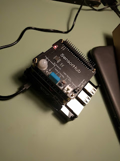
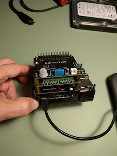
Finding a case for the Rpi 3b+ I've been through Argon One, and several others settling on a layered "kit case" which sort of sand castle layers itself up from the backplane to however high you want.. I didn't need or want a Top since I planned to use these "hat" modules from 52pi.
So far I've got the Powerboard (has a CPU fan and GPIO pass-thru), a Four SPST relay board and a multiple Sensor board with three Temp sensors, Baromoter, Humidity, Light and Motion sensor all built into one board. In general the are accessed from the command line over the i2c bus using standard tools like i2cset or i2cdetect ect.. they work great.
There is also a LORA board for GPS and GPRS (low speed Internet over cell radio) which I have but haven't popped a Google Fi sim into yet.. I think its not super fast.. not sure what I'll use it for.. a headless Teamviewer session to a console window? I dunno.
I got a Lightning Detector i2c board with a solderless QWIIC connector from Sparkfun and that has been working well.. but I hear from people its not reliable on the i2c bus.. I saw this.. but only when something else was on the bus.. they say its because the Clock SDA (or something) gets mixed up and can't be reset without powering down the board.. so they recommend SPI instead. I guess I'll have to look into that.. but.. on RPi I do have it working and its been generating a lot of data from passing storms.. the data looks genuine and good.
I just got Cacti setup and was starting to create a data source and graph for plotting the total number of strikes versus Time.
My goal is to use the Cacti Threshold plugin Trigger command feature to safeguard a DSL line by breaking the two wire connection to the ISP (and) switching off a USB controlled power monitor and surge protector.. while the RPi hides out behind all this attached to a good sized smart UPS with yet another USB connection to the RPi.. if either the strikes falls to zero.. or the UPS battery gets low.. the RPi can try to enable mains power to recharge the UPS before its totally out of power.
Its quite the project.. but we've had a well house and pump freeze and burst, a new refrigerator fail due to lightning and I've had many DSL routers literally "smoked" by lightning strikes.
I'm hoping this works out.. I couldn't find a cheap solution from Google, Home Depot or Lowes and nothing online that doesn't really work for the consumer.. only for something like a Data Center or a TV station.
As an example here is how to low effort manipulate the Relays:
pi@raspberrypi:~ $ i2cset -y 1 0x10 0x01 0xff + On
pi@raspberrypi:~ $ i2cset -y 1 0x10 0x01 0x00 - Off
pi@raspberrypi:~ $ i2cset -y 1 0x10 0x02 0xff
pi@raspberrypi:~ $ i2cset -y 1 0x10 0x02 0x00
pi@raspberrypi:~ $ i2cset -y 1 0x10 0x03 0x00
pi@raspberrypi:~ $ i2cset -y 1 0x10 0x03 0xff
pi@raspberrypi:~ $ i2cset -y 1 0x10 0x04 0x00
pi@raspberrypi:~ $ i2cset -y 1 0x10 0x04 0xff
And to read all the Sensors with a simple command line C program:
root@raspberrypi:~# ./sensor
No external temperature sensor!
Current onboard sensor brightness = 784 Lux
Current onboard sensor temperature = 29 Celsius
Current onboard sensor humidity = 35 %
Current barometer temperature = 29 Celsius
Current barometer pressure = 100829 Pascal
Live body detected within 5 seconds!
I haven't really got into the LoRA board yet.. but it looks like fun:
These are available through GeeekPi and Amazon or direct from China for pretty low cost and the build quality is actually really nice.
There is a Wiki with samples for Bash, Python and Java or C examples programs and quite a bit of documentation.
52pi.com Hat Stack
I hope they're doing well because you need very little in the way of soldering skills to connect all the modules and start programming. Its nice to have simple snap together IoT devices with "total control" from a Bash command line, script, or language.
Some of the details and a few instructions are lacking a character here or there.. but if they paid for a really good translator.. I'm sure it would raise the price of these really nice modules.
Normally I like the Google Nest products.. and I still do a lot of that.. but their organizational changes and Googles habit of canceling things without warning has got me back in the mode of "Can I do this myself?"
I had been enthralled with the $5 PiZero for a couple years.. and barely got Teamviewer or VNC server to work on one.. mostly through x86 emulation.. and that was not easy.
This year I finally upgraded to RPi 3b+ just before the RPi 4 came out and got the Teamviewer 11 beta/prototype for linux armf (?) architecture to work.. and it was astoundingly good.

All that I wanted and none that I didn't want.. and it integrated into whatever contacts list I had for my personal or work teamviewer account.. really nice.
I'd experimented with DynDNS way back in the day to build a dynamic router that would bridge ports to services on things on a local lan out to the cloud.. but security and ISP stability pretty much killed that effort. Teamviewer handles a lot of that backend and now that its on Linux (Raspbian) it was just low effort and great.
Finding a case for the Rpi 3b+ I've been through Argon One, and several others settling on a layered "kit case" which sort of sand castle layers itself up from the backplane to however high you want.. I didn't need or want a Top since I planned to use these "hat" modules from 52pi.
So far I've got the Powerboard (has a CPU fan and GPIO pass-thru), a Four SPST relay board and a multiple Sensor board with three Temp sensors, Baromoter, Humidity, Light and Motion sensor all built into one board. In general the are accessed from the command line over the i2c bus using standard tools like i2cset or i2cdetect ect.. they work great.

I got a Lightning Detector i2c board with a solderless QWIIC connector from Sparkfun and that has been working well.. but I hear from people its not reliable on the i2c bus.. I saw this.. but only when something else was on the bus.. they say its because the Clock SDA (or something) gets mixed up and can't be reset without powering down the board.. so they recommend SPI instead. I guess I'll have to look into that.. but.. on RPi I do have it working and its been generating a lot of data from passing storms.. the data looks genuine and good.
I just got Cacti setup and was starting to create a data source and graph for plotting the total number of strikes versus Time.
My goal is to use the Cacti Threshold plugin Trigger command feature to safeguard a DSL line by breaking the two wire connection to the ISP (and) switching off a USB controlled power monitor and surge protector.. while the RPi hides out behind all this attached to a good sized smart UPS with yet another USB connection to the RPi.. if either the strikes falls to zero.. or the UPS battery gets low.. the RPi can try to enable mains power to recharge the UPS before its totally out of power.
Its quite the project.. but we've had a well house and pump freeze and burst, a new refrigerator fail due to lightning and I've had many DSL routers literally "smoked" by lightning strikes.
I'm hoping this works out.. I couldn't find a cheap solution from Google, Home Depot or Lowes and nothing online that doesn't really work for the consumer.. only for something like a Data Center or a TV station.
As an example here is how to low effort manipulate the Relays:
pi@raspberrypi:~ $ i2cset -y 1 0x10 0x01 0xff + On
pi@raspberrypi:~ $ i2cset -y 1 0x10 0x01 0x00 - Off
pi@raspberrypi:~ $ i2cset -y 1 0x10 0x02 0xff
pi@raspberrypi:~ $ i2cset -y 1 0x10 0x02 0x00
pi@raspberrypi:~ $ i2cset -y 1 0x10 0x03 0x00
pi@raspberrypi:~ $ i2cset -y 1 0x10 0x03 0xff
pi@raspberrypi:~ $ i2cset -y 1 0x10 0x04 0x00
pi@raspberrypi:~ $ i2cset -y 1 0x10 0x04 0xff
And to read all the Sensors with a simple command line C program:
root@raspberrypi:~# ./sensor
No external temperature sensor!
Current onboard sensor brightness = 784 Lux
Current onboard sensor temperature = 29 Celsius
Current onboard sensor humidity = 35 %
Current barometer temperature = 29 Celsius
Current barometer pressure = 100829 Pascal
Live body detected within 5 seconds!
I haven't really got into the LoRA board yet.. but it looks like fun:
These are available through GeeekPi and Amazon or direct from China for pretty low cost and the build quality is actually really nice.
There is a Wiki with samples for Bash, Python and Java or C examples programs and quite a bit of documentation.
52pi.com Hat Stack
I hope they're doing well because you need very little in the way of soldering skills to connect all the modules and start programming. Its nice to have simple snap together IoT devices with "total control" from a Bash command line, script, or language.
Some of the details and a few instructions are lacking a character here or there.. but if they paid for a really good translator.. I'm sure it would raise the price of these really nice modules.
8/17/2019
Where I've been.. and going
So I've been a busy person this year.
In February I noticed an odd quirk in a Toshiba RD-XS32. Its a DVD recorder with a hard drive. I took the hard drive out and put it in a PC and started looking at the bytes on the hard disk.
Not knowing the binary editor I was using too well.. and messing up on the unicode representation.. I found what I thought were "reversed" bytes in the data stream. Not only that. I didn't understand it at the time but they were (Not) Big Endian vs Little Endian reversals.
Rather they were a straight forward byte swap every 8 bits.
I'd been looking at a data recovery tool called IsoBuster, and decided to open a support ticket and see if he could make sense of the data a little more.
In the mean time I found that the Linux DD tool from ibm UNIX days had acquired a swap bytes while copy option.. and copied the hard disk to another hard disk.. then mounted it as a UDFS.. it turned out to be readable.
It wasn't readable as in title names for recordings.. but rather in some strange and new VR/VRO format I was not familar with.
Fortunately the author of IsoBuster was nearly familar with it.. and with a little prodding and comparing with the VRO format from a Panasonic DVD-RW.. and some clues left on a website years ago.. he was able to knit the files and titles back together in a virtual file system which made complete sense to a newbie like me.
And I thought that was the end of the story... turns out.. not.
I then found the same thing worked for all of the Toshiba model DVD recorders with hard drives.. they had been recently falling in price on eBay.. so I collected a few of them. Each one worked perfectly.
I then noticed you could swap the hard drives back and forth between the Toshiba models and the recordings previously made on one recorder would work on the the other model. Super.
I accidentally found out that an SD card to IDE adapter would also work on the Toshibas and completely format and replace the hard drives in the recorders.. so even if I couldn't find an IDE hard drive.. I could use SD cards in their place and make and play back new recordings.. or eject those SD cards and read them on a PC with the augmented IsoBuster program. Awesome.
In previous years I had discovered that specific hard to get models like the RD-XS54 and RD-XS55 could upload or copy (that is "dub") their recordings in their original format via a built-in function based via a kind of FTP using the hand held remote control to a normal Windows PC, running a python program or Windows Delphi (pascal) program and could in theory to a Mac as well. But directly copying from drive to drive via IsoBuster was far faster and superior.. and from SD card to hard drive just as conveneient.
From the Toshiba things kind of spiraled outwards.. the author of IsoBuster and myself discovered as I collected DVD/HDD recorders that almost all "were not encrypted" and the "filesystems" on these devices were actually in some form of very well understood and published VR/VRO or customized FAT file systems.. there was a pattern that they seemed to not be able to escape.
I think this due to their low power CPUs and using off the shelf "kits" for capturing and encoding signals from camcorders or tv/cable broadcasts to their hard disks. They couldn't stray too far from the intended VR/VRO formats used by camcorders to get them ready for burning to a DVD+/-R blank.
So by and large the differences reflected only those changes to support specialized marketing features like "timeshifting" or "video catchup" or "live replay" modes. This resulted usually in slightly fragmented or "leader in/out" tags at the front and rear of a recording on those recorders that had the feature.. but most of the time a simple trimming of the recording would be all that was necessary if desired to cut it down to exact recording length.
Besides being "Faster" to copy recordings from the original DVD recorder hard drive to a PC hard drive.. the recordings could be made in different Picture Quality modes called "speeds". Some even higher that the "speed" that DVD movies are released in, and of even better quality. So where burning a DVD typically require "downsizing" and "making the Picture Quality (worse)" to fit on a DVD.. and making it necessary to "chop up" DVD recorder recordings so that they could fit on single sided or double sided DVD media.. you didn't have to sacrifice the Picture Quality.. or the program length.. no editing (at all) was required to begin copying the recordings from the DVD recorder hard drive to a PC.
The format of the DVD recorder hard drives recordings were invariably in a type of MPEG2 recording format interleaved with additional program information.. sometimes as .VOB files. The software playback community had long ago figured out how to identify and play these back on a PC.
So once the recordings were recovered it was merely a matter on a Mac or PC of getting something like VLC to play them back, convert them to other formats.. or sometimes Quicktime and Windows Media Player just played them without any additional problems.
As MPEG2 even high bit rate non-DVD standard video files.. editing does have a few challenges.
First it wasn't until "end point" healing or re-encoding only on "cut points" came about in programs like VideoRedo.. that people could venture back and cut out bad scenes, commercials or other unwanted clips.. to save storage space, improve pplayback continuity and make things better for sitting down and watching a program.
Today many programs can "edit" out clips in a long MPEG2 video and even re-encode it to a DVD standard that can be burned to DVD or Blu-Ray blanks.
So.. stumbling along blindly.. we ended up adding support for the Toshiba, all of the Pioneer DVD recorders, most of the Panasonic DVD recorders and some of the Panasonic Blu-Ray recorders, Maganavox, Philips and a few others. It was a massive effort.. but my role was mostly in that of a clean white-room style "testing" of updated versions of IsoBuster.. while providing feedback to the author "didn't work.. or almost worked".
He was located over 7000 miles away in a foreign country.. and we have never met in person. I was simply a customer who bought a copy of his software and inquired about supporting a particular DVD recorder hard disk format.. it kind of grew from there.
Uncompressed bit for bit identical video capture is preferred if your trying to correct or "fix" video capture from a VHS recorder. The truth of the matter however is it still produces very large capture files which few people have the time or money to store and then fix large files. So while its coming down in costs.. its still a very difficult thing to achieve here in mid 2019.
And monitoring and course correcting VHS playback requires an enormous amount of personal time, when most people would rather toss in a tape, play it back and go to the gym and come back to a completed capture. Some won't even look at the capture for years.. long after the tape is destroyed or thrown away. For these situations using a DVD/HDD recorder is ideal.. and being able to offload or export the recordings to a PC more so.
I've read even the United Nations had many historical interviews they wanted to convert from aging video tape to a digital format accessible from a PC in some sort of databank. Using DVD / HDD recorders that IsoBuster currently supports would be ideal for this.
Just two months ago Verbatim announced it would be selling its brand name and all assets to CMC, a competitor who made DVD and Blu-Ray blanks of questionable quality. And not known for making blanks that could be recorded on by older DVD / HDD recorders.. so the end of that media format seems near. It may be possible to continue with PC DVD or Blu-Ray burners in the near term.. but the time to think abut ripping things stored on DVD and Blu-Ray media is here.. ripping back to magenetic storage like PC hard drives.
We never successfully figured out how to "copy" from the hard drive of a JVC - DVD / HDD recorder to a PC drive with IsoBuster. We sort of ran out of time or motivation, and it was somewhat different.. yet another custom file system.
A lot of interest and motivation in the project has fallen by the wayside and not a lot of "good" commentary has followed.. more apathy, or complaints that this should have been done ten years ago.
Hindsight may be foresight.. but in my case.. I was too young, broke or in some countries "poor" to afford touching a DVD recorder.. let along own one.. so it might have been a good idea to do it that long ago. But I simply can't imagine any scenario in which I would have been involved.
There is also a lot of negativity about the idea that it was possible.. many, many people said it was all encrypted and dreamed up conspiracy theories about how hollywood was driving the tech industry and directing what they did. I'm not sure of that.. and don't mean to knock any of that ornate and elegant storytelling down.. but we never found encryption on anything.. technically the CPUs back then just didn't have the power.
We sort of suspect encryption in one or two models and immediately ceased investigating them.. our guiding rule was not to infringe or aide in any violations of laws. Its the plain truth however that this was mostly a data recovery effort of whatever the previous owners had stored on their hard drive. Macrovision and other schemes were not circumvented and the recorders were not modified to enable violations.. this was simple data recovery.
So that occupied most of my time until mid July.
Now I'm not sure of what I'm doing.. I've been engaged in a lot of Raspberry Pi 3+ efforts with a lightning detector to automate safe guarding the power supply and DSL lines to my Moms rural home. DockerPi has played a large part in that.. I really like their Pi "Hats" which offer pass-thrus for all of the GPIO pins.. and a fan module.
Some Apple Mac Vintage Video capture devices from Grass Valley have caught my eye.. since they capture in 4:2:2 mode as Motion Jpeg, Apple Intermediate Codec and Uncompressed.. and still work all the way up to OS X 10.12 Sierra.
1/20/2019
DVD packet attachement communications (ATA over IDE)
CDROM and Tape drives were common devices added to the IDE bus. Floppy Disk drives like the LSI optical laser guided floppy disk also made their way to the IDE bus.
The IDE bus was essentially "like" the SATA bus except it was "Parallel" and based upon treating the device as a "Logic Chip" with an established procedure to "signal" to the CPU or other chips on the bus that a "Parallel" byte or word was ready to be read on the IDE bus.
For the "controlling" or (host) device in the communication it would take control of the data lines and set their "state" to represent the data byte or data word it wanted to "send", it would then use a control line on the bus to signal "ready".
For the "device" or (client) device in the communications it would passively "read" the state of the data lines to determine the byte or word and copy that to its local memory space then raise another signal line on the bus to signal "done" or "transmission complete".
In this ratchety, lock step manner, bytes could be copied from host memory to device memory and byte "flipping" who was the (host) and the (client) data could be sent back. This procedure was ironically also called "Clocking" the data into and out of a device since it was assumed the devices on either side of the bus shared an asynchronous "clock" with wide enough "gaps" between communciations and running at approximately the same speed to not corrupt the data in transmission.
The contents of the bytes and what to do with them were "encoded" within as a kind of "data control language" and would indicate "where" to store the data on a disk for example, or ask for data at a specific location on a disk to be retrieved.
The first "data control language" was very simple, it was that used to control a hard disk.
Extending the "data control language" was known as "the Packet language" and consisted of an abreviated subset of the SCSI bus data control language. Just enough to communicate with a limited number of additional device types like the CDROM, Tape drives and Floppy Drives for IDE and later the DVDROM reader and burner.
Today it lives on in SATA form for controlling Blu-Ray multilayer optical disc reader and burners.
After an initial technical working group established the format for ATA communications, additional device manufacturers would come together and write "Specifications" for the control language which would control their devices over the IDE/EIDE/ATA data channel irrespective of the hardware specifications for the actual physical bus and connectors.
"Specification language" is hard to read. It rarely includes "examples" of what is actually being discussed. In part because at the time of the "Spec document writing" no real world example exist as a product.. so they can appear necessarily "vague" and un-tethered from "reality" once actual products come on the market.. at best.. they are "first approximations" or "guesses" as to how something "will work" regardless of the intentions of the document to specify "how they should work correctly".
Sometimes "Patent" filings reveal how a particular manufacturer "intends" to implement an actual working product based on their interpretation of the Specification. However its more common to keep these as obscure trade secrets.
"FCC" filings sometimes provides a little more detail, but not much as the applicant can request certain details be removed from the public record.
1/07/2019
IDE interface for microcontrollers
IDE or EIDE is a hard drive via host controller interface generally used for connecting hard drive, cdrom drives and tape or floppy drives to an IBM style PC. Its kind of well documented but not succinctly.
It emerged as a replacement for the ST506 or Shugart Technologies MFM drive and controller combination. Shugart was known for developing the 5 1/4 inch floppy disks of the 1980s among other things.
The idea for the interface was to "offload" the mangement of positioning the heads and control of the reading of the disk as much as possible to a microcontroller onboard a seperate "controller" for the hard drive.
To the PC however this is presented as a device connected to the 8 bit ISA bus.
The 8 bit ISA bus was capable of transmitting 16 bits at a time, but for early equipment 8 bits was the maximum. Address and decoder logic circuits to actuate and pulse control lines would indicate to the connected HDD controller when commands were ready on the bus to be read, and whether the PC were ready or had finished offloading data from the HDD controller memory "buffer". and into the PC memory. Write to the HDD wass accomplished much the same way by "presenting" data on the bus, and then pulsing or actuating control lines to indicate to the microprocessor on the HDD controller card that data was ready to be read.
Initially the PC understood or had to make it requests assuming the HDD were made of Cylinders, Heads and Sectors.. corresponding to the location of "blocks" of data of approximately 512 bytes of data per block. Due to the size of the data types used to access the HDD by the 8 bit (and later 16 bit) BIOS, limits on the Total size of "addressable" storage on HDD were imposed.
Physically however HDD had limits on the actual number of Heads in a drive, but the data type for this number was confiscated and reused as a "general" variable for a virtual drive with many more heads than physically possible. The HDD controller then could translate that into a method for accessing larger and larger HDD storage capacity. But to get away from proprietary "translations" it became common place to begin using all of the CHS "bit space" to represent a linear 24 bit adress call a "Logical Block Address" or LBA. Later LBA technology would get an upgrade to LBA-48 to access even more storage.
To a PC it has been said the HDD "looks like a chip" attached to its mini-ISA or IDE bus. It communicates to this "chip" using memory and address and control lines.
The speed at which the PC communicates when reading or writing data is an interpretation of the result of sending commands, waiting for the HDD to raise a "ready" line and then offloading that data into its memory. And vice versa for writing.
HDD limitations due to "seeking" or "retries" of sectors are hidden or delt with by the HDD controller but can be reported to the PC if queried.
PC limitations due to "calculation" time for locating a file in a virtual file system that exists as a consequence of storing a pattern on the hard drive with an indexing system are hidden or delt with by the PC.. but do add to time required to retrieve or write data.
A simple microcontroller that wishes to access an IDE hard drive merely needs to have enough 5 volt buffered ISA lines corresponding to the subset of the ISA bus lines that define an IDE interface.
Many microprocessors today have only 3.3 volt I/O lines, and these must be protected or buffered by sufficient interface circuits or buffer chips.
The protocol for actuating control lines and presenting data to an IDE connected drive are documented by timing diagrams, but in general PIO - Programmed Input Output access mode is under the control and speed of the host microprocessor.
Microprocessors with custom peripherals or FPGA defined co-controllers to offload the task of communicating over a built-in IDE interface were more common at one time from Freescale.. but have passed mostly into history. Today discrete chips to create a supporting IDE interface are less common but can still be done.. though SPI and software defined FPGA circuts to provide that function are becoming more common.
Its quite common in fact to redefine the IDE bus as a chip function as part of of a more general purpose USB attached peripheral, and that as a SATA device and then attach a SATA to IDE interface to complete the connection.
This minimizes the electrical demands and potential incompatibilites of custom designed circuits.
Subscribe to:
Posts (Atom)